
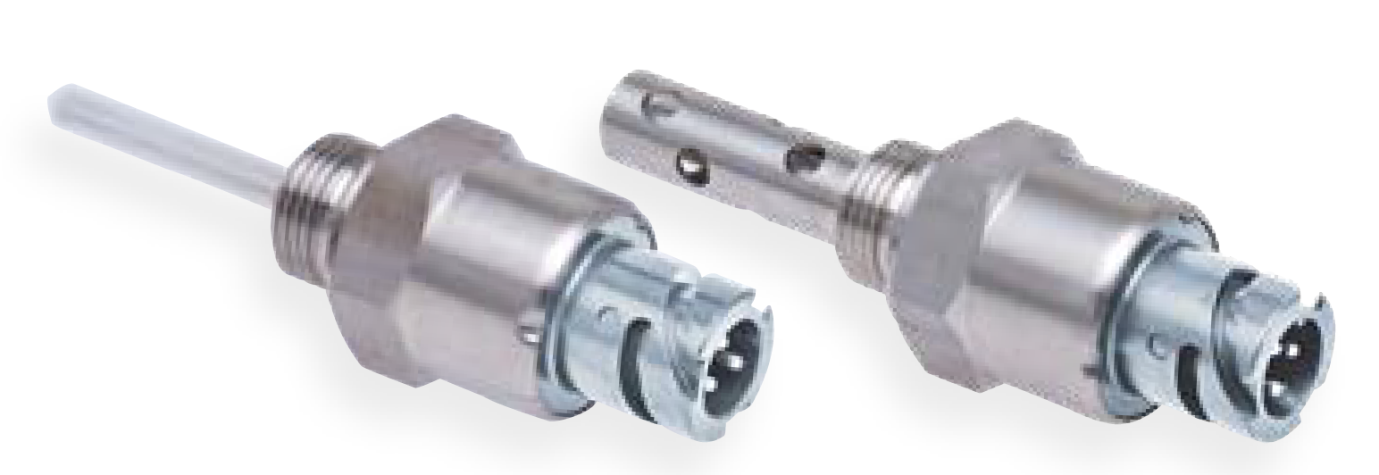
A SHR level monitoring sensor is a device that is used to monitor the level of liquids in a tank or other container. The sensor consists of a probe that is inserted into the tank, and a controller that is located outside of the tank. The probe is connected to the controller by a cable.
Principle:
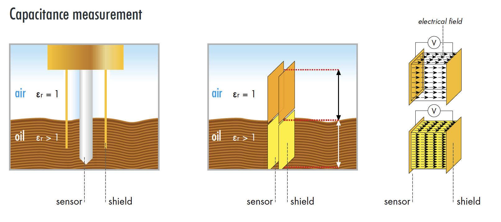
The operating principle of a SHR level monitoring sensor is based on the capacitive principle. A capacitor is a device that stores energy in an electric field between two conductors. The amount of energy stored in a capacitor is proportional to the capacitance of the capacitor, which is determined by the size and shape of the conductors and the distance between them.
In a SHR level monitoring sensor, the two conductors are the electrode and the liquid medium. The electrode is a metal rod that is inserted into the tank, and the liquid medium is the liquid that is being monitored. When the electrode is inserted into the liquid, the capacitance between the electrode and the liquid increases. This increase in capacitance is detected by the sensor and is used to determine the level of the liquid in the tank.
The sensor is typically calibrated to detect the level of the liquid in a specific range. For example, the sensor may be calibrated to detect the level of the liquid in a range of 0 to 100%. When the level of the liquid is at 0%, the capacitance between the electrode and the liquid is at its minimum value. When the level of the liquid is at 100%, the capacitance between the electrode and the liquid is at its maximum value.
The sensor can be used to detect the level of a variety of liquids, including water, oil, and gasoline. The sensor is also resistant to vibration and can be used in harsh environments.
The probe contains a sensor that detects the level of the liquid in the tank. The sensor sends a signal to the controller, which then displays the level of the liquid on a screen or sends a signal to an alarm.
SHR level monitoring sensors are used in a variety of applications, including:
- Engine monitoring
- Fuel monitoring
- Water monitoring
- Wastewater monitoring
- Bilge monitoring
SHR level monitoring sensors are available in a variety of models, each with its own set of features. Some of the features that are available include:
- Remote monitoring
- Alarms
- Data logging
- Wireless connectivity
SHR level monitoring sensors are a valuable tool for businesses and organizations that need to monitor the level of liquids in their tanks or containers. The sensors are accurate, reliable, and easy to use.
Here are some of the advantages of using a SHR level monitoring sensor:
- Accurate: The sensor detects the level of the liquid in the tank with high accuracy.
- Reliable: The sensor is reliable and will not fail easily.
- Easy to use: The sensor is easy to install and use.
- Remote monitoring: The sensor can be monitored remotely, which is useful for businesses that have multiple locations.
- Alarms: The sensor can be set to send an alarm when the level of the liquid reaches a certain point.
- Data logging: The sensor can log data about the level of the liquid, which is useful for businesses that need to track the level of the liquid over time.
- Wireless connectivity: The sensor can be connected to a wireless network, which allows it to be monitored and controlled remotely.
Minimum Sensor
The SHR level monitoring sensor has two types of outputs: a working current output and a quiescent current output. The working current output is active when the sensor is immersed in the medium, and the quiescent current output is active when the sensor is removed from the medium. The output is deactivated instantaneously when the sensor is immersed in the medium, and the output is activated after the fault indication delay time when the sensor is removed from the medium.
The working current output is used to control a device, such as a pump, that is used to maintain the level of the liquid in the tank. The quiescent current output is used to monitor the level of the liquid in the tank. The output is typically connected to a controller, which will send an alarm if the level of the liquid falls below a certain level.
The fault indication delay time is the amount of time that elapses between the sensor being removed from the medium and the output being activated. The fault indication delay time is necessary to prevent false alarms from being triggered by small fluctuations in the level of the liquid.
Maximum Sensor
A maximum sensor is a type of level monitoring sensor that is used to detect the maximum level of a liquid in a tank. The sensor is typically installed in the tank so that the electrode is submerged in the liquid. When the liquid level reaches the maximum level, the electrode will be immersed in the liquid and the sensor will send an output signal.
The output signal from a maximum sensor can be used to control a device, such as a pump, that is used to maintain the level of the liquid in the tank. The output can also be used to monitor the level of the liquid in the tank. The output is typically connected to a controller, which will send an alarm if the level of the liquid reaches the maximum level.
The fault indication delay time is the amount of time that elapses between the sensor detecting the maximum level of the liquid and the output being activated. The fault indication delay time is necessary to prevent false alarms from being triggered by small fluctuations in the level of the liquid.
When the maximum sensor is removed from the medium, the output is deactivated instantaneously. This is because the electrode is no longer submerged in the liquid and the sensor is not able to detect the level of the liquid.
M14 x 1,5 9-36 V DC MIN 0 7 – – – – – 500 320 500 113 500 314
M18 x 1,5 9-36 V DC MIN 0 0 – 500 170 – – – – – 500 114
M18 x 1,5 9-36 V DC MAX 0 0 – – 500 063 500 171 – – – 500 297
M18 x 1,5 9-36 V DC MAX 0 3 – – – – – – 500 108 –
M18 x 1,5 9-36 V DC MIN 0 7 – – – – 500 038 – 500 110 500 265
M18 x 1,5 9-36 V DC MAX 0 7 500 014 – 500 068 – – – 500 115 500 112
M18 x 1,5 9-36 V DC MAX 2 3 – – – 500 257 – – – –
M18 x 1,5 9-36 V DC MIN 2 7 500 015 500 091 500 065 500 069 500 039 500 041 500 188 500 189
M18 x 1,5 9-36 V DC MAX 2 7 500 010 500 013 500 064 500 067 500 040 500 190 500 111 500 191
M18 x 1,5 9-36 V DC MIN 0 20 – – – – – – – 500 109
M18 x 1,5 9-36 V DC MAX 0 20 500 011 – 500 070 – – – – –
M18 x 1,5 9-36 V DC MIN 2 20 500 012 – 500 066 – – – – –
G 1/2“ 9-36 V DC MIN 2 7 – – – 500 270 – –
M18 x 1,5 9-36 V DC MAX 0 0 – 500 229 – 500 231 – 500 234 500 104 500 236
M18 x 1,5 9-36 V DC MIN 0 7 – 500 230 – 500 232 – 500 035 500 107 500 088
M18 x 1,5 9-36 V DC MAX 0 7 500 007 500 203 500291 500 207 500 034 500 211 500 100 500 213
M18 x 1,5 9-36 V DC MAX 0 7 500 289 * – – – – – – –
M18 x 1,5 9-36 V DC MIN 2 7 500 008 500 192 500 061 – 500 037 500 036 500 106 500 089
M18 x 1,5 9-36 V DC MAX 2 7 500 009 – 500 059 – 500 233 – 500 235 –
M18 x 1,5 9-36 V DC MIN 0 20 – – – 500 062 – – 500 087 500 086
M18 x 1,5 9-36 V DC MAX 0 20 – – – – – – 500 103 –
G 1/2″ 9-36 V DC MIN 2 7 500 201 – 500 205 – 500 209 – 500 101 –
G 1/2″ 9-36 V DC MAX 2 7 500 200 – 500 204 – 500 208 – 500 085 –